Thursday, November 27, 2014

Happy Thanksgiving!

Yesterday Kristi and I caught sight of the Sea for the first time in many months -- 11+ for her, perhaps only 3 or so for me, if you count my week back at Viking Star in August.  But I will say, it feels like 11+ months..

We not only saw the sea, we did the right thing - tossed our shoes and took a walk.  

After a day of driving, we arrived in time for the sunset.

There we go!


Happy Faces...


All around!


And there we are - back on the West Coast in Santa Barbara, CA.   These days we have tossed our coats (it was -11f this morning back in Storden MN, yes.  MINUS 11. . . .)  We are working our way slowly up the coast.  Monterey tonight, San Francisco tomorrow - will figure the rest of the days as they come.  Today, not wanting to lose sight of the sea, we took Hwy 1 up the coast.  After an hour or so Kristi managed to let go of the passenger seat (and she was not even using her hands!) long enough to take some pictures, might post some soon (or check out her Facebook page).

And FWIW, I was 10 years old the last time I was on California Hwy 1.  It is a great trip.  We played Old-person-mode, just driving nice and easy.  Well, not quite Old Person mode  - we pulled over several times to let traffic pass, even an RV - and maybe a VW at one point :-)

But be clear -North we are pointed!


Friday, November 21, 2014

Open source MPPT controller

OK, this is somewhat boating related :-)    As part of the other battery charging projects I have been doing (ala, DC generator, Alternator Regulator), I have now turned to three new areas:
  1. Solar MPPT controller
  2. Battery BMS
  3. CAN based network connecting all charging sources together...
I started doing this after observing some interesting interactions between different charging sources.  For example on Viking Star we have Solar + the mains alternator, and our little Kubota DC generator for energy sources while away from the docks.  Ideally one would like to see each of these sources (and yes, they CAN be all enabled at the same time) working towards the same goals; e.g., all having the same idea what target voltage should be, or when the battery is ready to move from Bulk to Acceptance phase.   In practice, each has their own idea and I can at times see undesirable interactions between them.  The target battery voltage from the Alternator might be a bit higher then the solar panels - and when things get to the final stages of recharging, the solar panels enter Float mode early, while leaving the mains alternator still charging.  Would be better if it was the other way around, turn off the mains alternator and let the the solar panels finish things up.

There are ways to 'work' around this, assuming equipment has the flexibility and configuration options.  Example, could set the Solar controller to a higher target voltage.  But that can leave the battery undercharged if working only on mains alternator (ala on a cloudy day) as the Alternator would need to be set for a lower voltage.  My vision is a 'systems' approach, a device installed on the battery would decide what the battery needs and communicate those needs to all charging sources.  This way everyone is working towards the same goal.  And it can reduce the wiring mess as well - we have 6 devices sampling battery temperature and voltage on Viking Star.  Those 12 sets of wires can be replaced with one CAT-5 cable.

I am just getting started on this, and have been working on a couple of hardware developments:

Each of these will communicate over a CAN network via CAT-5 cables.  Once I have those two working, will revise the Alternator regulator to participate in this system, and the DC generator as well.

Still have a lot of work to do, the two developments + the CAN protocols (am hoping to leverage on of the existing protocols out there), but today I just posted up the 1st cut hardware design for the solar MPPT controller.


Like my other projects it is open source and I have posted all the CAD files; will add the firmware as it gets developed.

Another reason I kind of think this is Boat Related: more then one of these controllers can be used on your boat and act in a coordinated way (due to the CAN).  For example, on Viking Star we have two solar panels.  At times one panel gets partly shaded.  Depending on how things are wired up, a partial shaded panel can either constrain the output of the whole system,  drop the whole panel out of participation, or some combination in between.   A separate MPPT controller dedicated to each panel should be able to fully optimize each panel, allowing the shaded panel to participate as much as it is able to, without impacting the other panel.

Design calculations look that this could come in under $100 in cost, and operate in the 98-99% efficiency range.  Am just now ordering hardware to build one up and look forward to trying it out next year on Viking Star.


Thursday, November 20, 2014

Basking in the Warmth of Colorado Springs!

It was a nice, but long, 14 hour drive from Storden, MN to Kristi's sister house in Colorado Springs CO.  We have enjoyed good company, sharing stories and memories, and the nice warm weather of Colorado in November.  (Today is forecasted for a high of 49f, NOAA is thinking Storden will make 16...)

Not too much more today, will perhaps do a reflection of the past year sometime soon.  Right now our thinking is head South say Monday, then over the California coast to the land of 'Happy Cows'.   Do a slow drive up the Pacific coast highways to Portland for the Christmas holidays; stopping for a few days in San Franscisco.  Then some time around New Year make our way back to Friday Harbor.  

But who knows, we do not really have any 'plans' these days :-)


Sunday, November 16, 2014

Tuesday it is...

Weather reports (aka, 'weather WAG')  tells us Tuesday is the day.  
  • We will finish up our 'business' - helping Dean tidy up Maynard and Ellen's financial affairs -  Monday (I hope).  
  • The Cat has gone to a new home,  a couple of weeks ago.  Kristi and I still expect to see 'Kit' at the door as we come in.  
  • DISH shut off the satellite service a few days early, and I was not able to enjoy 'CBS Sunday Morning' with my cup of coffee, fresh baked Cinnamon rolls, and my wife.

Yup, all stars are aligning - and we will look to be hitting the road Tuesday.  Bright and Early, 12-14 hour drive to Colorado Springs to spend a few days with Kristi's sister and brother-in-law.  Then looking to head to San Fransisco to visit Pip the Cat  (  http://pipsalbum.wordpress.com/about/ ) for Thanksgiving and a slow drive up the coast to Portland for the Christmas holidays.

New Years on Viking Star.

These past days have been a mix:  Visiting, packing, sorting, remembering, mourning, 'planning'.    Now will begin a time for transition.  Looking back Kristi and I are clear - we have no regrets taking this year off from cruising, with all its ups and downs.  And we do hope we brought something to Maynard and Ellen as their lives came to a close.  We think we did.

I put the Cruising Lifestyle label on this post because much of the 'lifestyle' is about Family.  Those we take with us and those we leave behind as we depart on our 'craziness'.  What will happen to them? Will they forget us?  Will we ever be able to truely go back into a 'normal' life?

"The whole idea is Freedom . . ." 1 begins a famous quote from an admired cruising couple, freedom to make choices, to follow where life takes us.

And we did.  Now its time to start another chapter.


 1  "The whole idea is freedom.    Go simple,  Go cheap,  Go now."   -  Lyn Pardee.


Friday, November 14, 2014

Cost to not cruise - October 2014

As with September, October had a funeral in it, and with that a bit more on the Dining Out and Transportation costs.  Other than that, not too much different.  We are winding down this 'Not Cruising' phase of our life, looking to get on the road Tuesday or Wednesday of next week making our way back West.  Likely will finish out the year as a 'not cruising' summary, and then do some comparisons with the prior year.


(Click for larger view)


====================================================================

And now here is the standard explanation: If this is your 1st time looking at costs on our blog, and want some more background on why we are reporting what it costs to not-cruise on a cruising blog - well, we are taking a break by moving back to Minnesota to help out Kristi's folks.  And we thought it would be interesting to be able to compare our costs on Land vs. on Sea., see more here:   mvVikingStar.blogspot.com/.../cost-to-not-cruise-january

For reference here is a summary of what it did cost us to cruise last year:


For Reference, Costs for Cruising in 2013
Again, following the link above will give you access to more details, or you can click on the Costs label to the right for even more cost data.

Sunday, November 2, 2014

Proper wiring of batteries in parallel

This topic came up on one of the Emailing lists I subscribe to:  How to connect up batteries which are wired in parallel. The person has 12x  T105 batteries and wanted to make up 2 sets of 6 batteries in a 2x3 arrangement (2 in series for 12v, then 3 sets in parallel per bank).  His question was around the size of the jumper wires.  I offered some ideas and also suggested he make sure to connect to the 'opposite corners' of each bank.

In my attempt to find a photo to share I searched the web - boy, I am SO SURPRISED how many places just get it wrong, and how few (if any) really get it right...  In fact, the 'Do it this way' photo I sent actually had it wrong..  ARG.   So, rather then spend more time searching the piles-of-wrong, I made up this photo myself. 


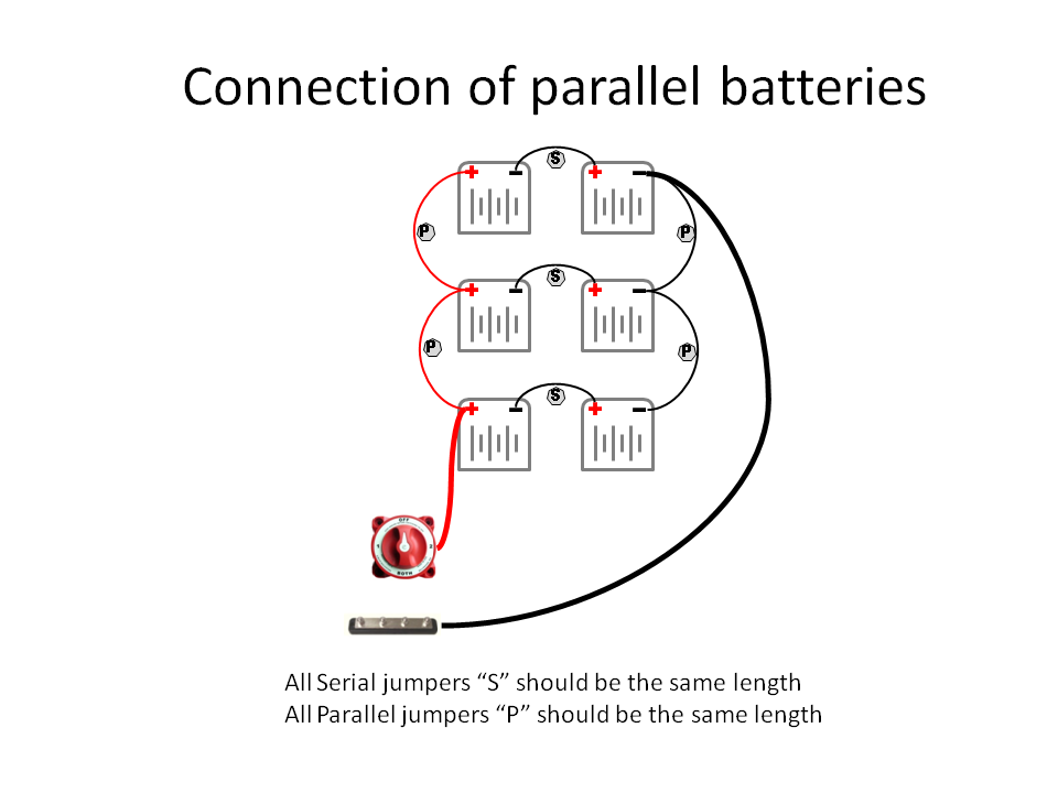
There are three key points in this photo:
  1. All the serial jumper wires (S) need to be the same size and length.
  2. All the paralleling jumper wires (P) need to be the same size and length, though the can be different than the serial jumper wires (S).
  3. The main feed wires are connected to opposite corners of the bank.

Why do this?   The idea here is to better balance heavy current draws.  By connecting at opposite ends we 'distribute' the losses equally.  E.g., the bottom battery gets no loss on the + side, but gets 2 jumpers worth of losses on the neg side (Need to remember both sides of a complete circuit).  The middle gets 1 jumper loss on both the pos and the neg, and the top battery gets 2 losses on the pos side and none on the neg side.  Note how each 
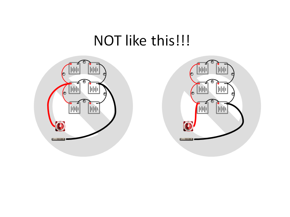
adds up to 2.  Contrast to these drawings:
In each of these cases there is an imbalance.  The example on the left with the heavy feed wires connected to the middle will overdraw the middle battery (it has no paralleling jumper losses), while the upper and lower batteries will each have 2x worth of losses.  (one + and one - paralleling jumper).  The example on the right is even worst, the middle battery still gets two losses, while the top batteries get 4!
 
Extending this concept further, if there are two 'banks' of these series/parallel batteries, again make sure the connecting wires are the same length to each bank, ala:

In actuality, it is the total length of each banks B+  combined with its GND wire that need to the the same.  Example you could put a 2' B+, and a 4' GND wire to bank #1, and then reverse things using a 4' B+, and 2' GND wire on bank two;  in each case the total length of the heavy feed wires will be 6', so both banks will see the same amount of loss. 


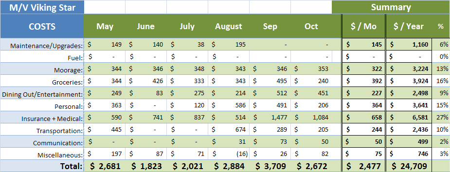
One might say:  But the losses are small and not worth dealing with.  I have been surprised just how much voltage drop one can have under high amp loads, ala at 220A our alternator creates over a 1/4v drop between the battery and the alternator - even though the main cable is MCM370 (3x sizes larger then 4/0 wire).  

True there are oh so many other things that will cause imbalances between batteries in a large parallel deployment.  Connectors crimped to the jumper wires, corrosion between connectors and battery terminals.  Battery variances themselves.  And losses are small - example:  a pair 16" - 1/0  jumpers at say a 100A will give only a 30mV loss.  Reality is most house batteries will dies for many other reasons then a small imbalance.  But I counter:  As we have a  choice in wiring, why not remove one contributor?


Should add here:  I am not a fan of placing several individual batteries in parallel, issues like the above  just come up.  I much prefer series connection of larger cells, ala replace the 12x - 6v T105 batteries above with 6x L16 form factor 2v cells all in series.  One would get the same capacity, longer life, and eliminate all these paralleling issues.

But if you must (and I know there are physical space limitations that come into play here as well), the above is how I would suggest connecting the banks up.